Bias Current Stability in Class A/B Car Amplifier Design
In Class A/B car amplifiers, controlling bias current is crucial for minimizing crossover distortion without causing excessive heat generation. Designers often use multi-stage thermal compensation, pairing bias transistors with temperature-tracking diodes or VBE multipliers mounted close to the output transistors. This ensures that as the amplifier warms up, the bias adjusts proportionally, preventing thermal runaway while maintaining linearity. Production lines equipped with AP testing platforms can verify that the bias remains stable under dynamic load and temperature variations.
Thermal Challenges in High-Fidelity Class A/B Topologies
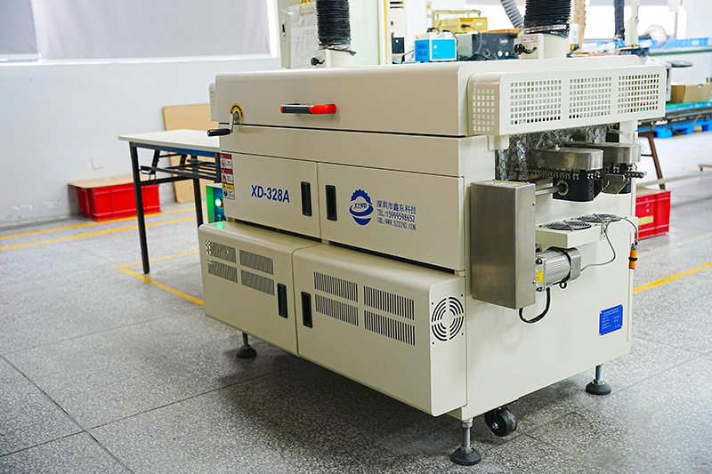
Class A/B car amplifiers dissipate significantly more heat than Class D designs, especially at moderate listening levels where the output transistors conduct continuously. High-power versions require large heat sinks, carefully placed ventilation slots, and thicker aluminum housings for improved conduction. To maintain long-term stability, factories implement 100% aging tests, allowing them to monitor thermal drift and detect solder fatigue or transistor mismatch under elevated temperatures.
Thermal Optimization Techniques
- Using thermal pads matched to transistor footprint for even heat spread.
- Integrating temperature sensors to activate protection circuits.
- Employing multi-layer PCBs with heavy copper for cooling assistance.
Output Stage Topology Choices for Enhanced Linearity
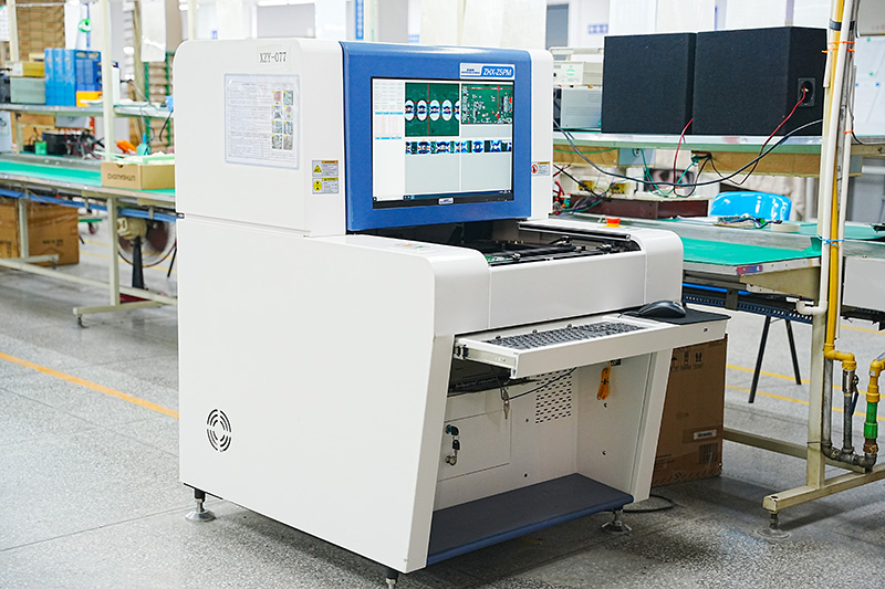
The output stage of a Class A/B amplifier heavily influences its tonal characteristics. Many premium designs use complementary emitter follower pairs to deliver symmetric drive with minimal distortion. Some advanced models employ triple-Darlington configurations, which improve current gain and reduce loading on the preceding stages. However, this increases PCB complexity and requires precise matching of transistor batches—an area where AOI inspection and controlled SMT processes provide major consistency advantages.
Power Supply Reservoir Capacity and Its Impact on Dynamic Headroom
Unlike Class D amplifiers, which rely on high-frequency switching supplies, Class A/B car amplifiers typically demand larger power supply reservoirs to deliver clean voltage rails under transient peaks. Large electrolytic capacitors with low ESR help maintain voltage stability during sudden bass hits or complex musical passages. High-quality production environments verify capacitor ESR, ripple handling, and temperature resilience to ensure long-term reliability even in harsh automotive conditions.
Common Reservoir Capacitor Specifications
| Specification |
Typical Requirement |
Purpose |
| Capacitance |
4,700–10,000 μF per rail |
Support transient power demands |
| Voltage Rating |
25–50 V depending on supply |
Provide margin for spikes and ripple |
| ESR |
Low ESR structure |
Reduce ripple voltage under load |
Distortion Management Through Multi-Stage Feedback Networks
Class A/B car amplifiers rely heavily on negative feedback to maintain low distortion. In advanced designs, a combination of global and local feedback loops is used—local feedback around the input and voltage amplification stages improves linearity, while global feedback stabilizes overall gain. Precision in component matching is essential; aging tests help detect drift in resistor values or transistor gains that could alter feedback characteristics over time.
EMI Performance Considerations for Analog-Dominant A/B Designs
Although Class A/B car amplifiers generate less high-frequency switching noise compared to Class D units, their analog circuitry is sensitive to vehicle EMI sources such as alternators, ignition coils, and digital modules. Designers may employ differential input stages, shielded signal paths, and carefully controlled ground routing. Modern AOI and SMT processes ensure consistent grounding geometries and shield placement, minimizing noise pickup across large production batches.
Practical EMI Control Methods
- Twisted-pair or balanced input connections.
- Dedicated ground reference paths for preamp stages.
- Shielded housing sections for sensitive analog components.
Mechanical Build Quality and Vibration Resistance
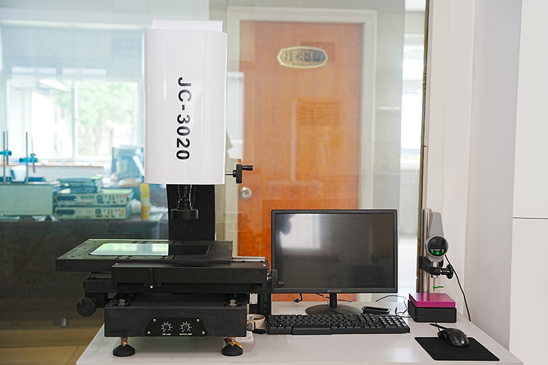
Class A/B car amplifiers contain heavier heat sinks and larger capacitors, making mechanical stability essential. Vibration in automotive environments can loosen fasteners or fatigue solder joints over time. Manufacturers reinforce the PCB with thicker substrates, install extra standoffs, and use locking compounds on screws. High-quality facilities also conduct vibration simulations to detect potential mechanical weaknesses before mass production.
Fine-Tuning Audio Signature Through Component Selection
The tonal character of Class A/B car amplifiers can be subtly shaped by selecting specific capacitors, op-amps, and transistor pairs. Film capacitors are often chosen for input filtering due to their superior linearity, while low-noise op-amps help preserve micro-detail. Matched transistor sets in the differential input stage reduce DC offset and improve stereo imaging. These component-level optimizations are most effective when combined with precision SMT placement and rigorous AP audio measurement.

 EN
EN
 English
 Español
 عربى
عربى


.jpg)
.jpg)