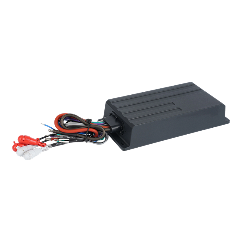
Advanced sealing techniques used to achieve IPX67 sealing and leak-proof structure
Achieving reliable IPX67-level protection requires more than a single gasket — it is a combination of material selection, multi-stage sealing processes, and verification. For ruggedized car and marine amplifiers, manufacturers commonly use sequential sealing steps: primary mechanical seals (O-rings or molded gaskets), followed by targeted potting or silicone bead applications at sensitive joints, and then a controlled adhesive sealing around cable entries. This layered approach reduces the probability of a single-point failure and improves long-term resistance to repeated submersion and thermal cycling.
Key sealing practices to reduce leak risk
- Design cable entry with a dedicated potted boot or strain-relief chamber to isolate the PCB from ingress paths.
- Use multiple adhesive curing steps with low-shrink, marine-grade silicones to avoid stress cracks created by differential thermal expansion.
- Perform controlled assembly in humidity- and dust-controlled environments to ensure adhesive bonds are not contaminated.
- Implement non-destructive air-leak testing per unit rather than sampling — an effective way to verify the applied sealing process for each amplifier.
Die-cast aluminum housings: corrosion, thermal and structural trade-offs
Die-cast aluminum heatsinks provide an attractive combination of thermal mass, rigidity, and manufacturability for IP-rated amplifiers. In marine and powersport environments the choice of alloy, surface treatment, and secondary finishing define both corrosion resistance and paint/coat adhesion. For true long-term reliability, anodizing or epoxy-based coatings plus targeted sacrificial coatings at fastener points are common practice. Note that improper surface finishing can create micro-galvanic cells in salt environments — targeted design mitigates this risk.
Practical specifications to request from suppliers
- Specify alloy grade (e.g., ADC12 or equivalent) and request lab corrosion data such as hours to first white rust in salt spray testing.
- Ask for surface roughness metrics post-casting to ensure coating adhesion consistency.
- Require documentation of coating thickness and dielectric breakdown where electronics proximity makes it relevant.
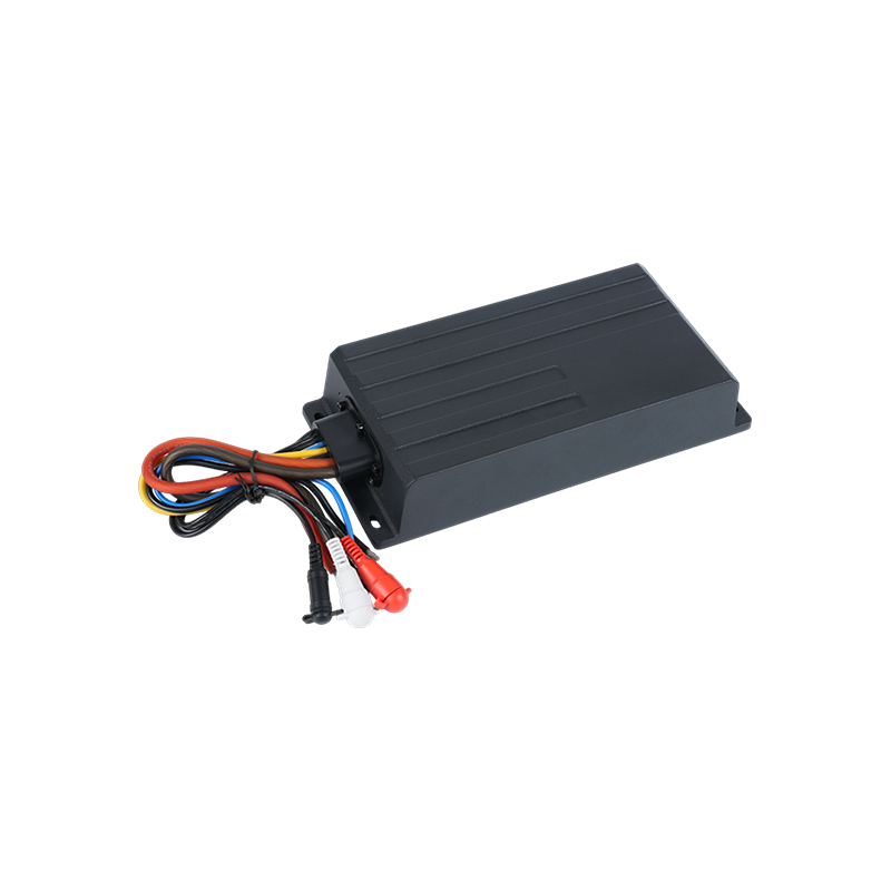
Pigtail wire-harness design and vehicle-specific connector customization
A pigtail harness that’s easy to integrate reduces installation errors and field returns. For powersport amplifiers, harnesses should support strain relief, keyed connectors to prevent mis-mating, and options for in-line fusing. Customizable connectors — either pre-crimped OEM-style plugs or modular adapter leads — allow a single amplifier SKU to serve multiple vehicle platforms while preserving IP sealing at the amplifier end.
Recommended harness features for installers
- Sealed connectors (IP67-rated) for all external interfaces: power, remote turn-on, and audio inputs.
- Color-coded conductors and clear documentation to speed up field wiring and minimize polarity mistakes.
- Provision for inline ferrite suppression and ground-lift options to manage EMI without modifying the amplifier housing.
Testing protocols that validate IPX67 and lifecycle durability
Passing an IPX6 or IPX7 Class Powersport Amplifier rating requires controlled submersion testing, but robust validation adds salt spray, UV exposure, vibration, shock, and thermal-shock cycles. A typical advanced QA sequence for marine-grade amplifiers includes salt spray per ASTM B117, 1000+ hours of accelerated UV exposure, multi-axis vibration per industry automotive profiles, and immersion followed by internal humidity monitoring. Combining these tests reveals failure modes that single-condition tests miss.
Practical QA checkpoints and acceptance criteria
| Test Type |
Typical Protocol |
What to Monitor |
| Water Immersion |
1 m submersion for 30 minutes (IPX7) |
No internal water, functional after test |
| Salt Spray |
ASTM B117, 96–1000 hours |
Corrosion level, coating integrity |
| Vibration |
Automotive multi-axis profile, hours-based |
Connector retention, solder/joint integrity |
Thermal management, Class D efficiency, EMI compliance and practical tuning
Compact Class D circuitry reduces power loss and allows smaller heatsink geometries, but under continuous high-load use (e.g., marine trolling motors or extended off-road audio sessions) thermal throttling can still occur. Die-cast aluminum housings double as heatsinks, but the interface between PCB and housing must use conductive gap fillers and thermally conductive adhesives to maintain low junction temperatures. EMI management is equally important; layout practices such as split ground planes, common-mode choke placement, and shielded input paths help achieve CISPR 32/CISPR 25 and FCC compliance without sacrificing audio performance.
Practical tuning advice for installers and system designers
- Use HPF/LPF and selectable mode settings to reduce sustained low-frequency thermal load on the amplifier in small enclosures.
- Mount amplifiers with open airflow toward the vehicle’s coolest airflow path; avoid closed compartments without ventilation even if the unit is IPX7-rated.
- When adding DSP or Bluetooth modules, verify any additional antenna or I/O penetrations are integrated into the sealing plan rather than retrofitted after production.
Taken together, these practical measures — from multi-stage sealing and verified salt-spray resistance to harness design, thermal interface engineering, and EMI-aware PCB layout — are what turn a standard amplifier into a truly ruggedized solution. When specifying an IPX6 or IPX7 Class Powersport Amplifier for marine or off-road use, require documentation of each of the above processes to minimize in-field failures and ensure consistent, leak-proof performance.

 EN
EN
 English
 Español
 عربى
عربى


.jpg)
.jpg)