EN
EN
 English
 Español
 عربى
عربىContent
- 1 Choosing the Right Car Amplifier Before You Start
- 2 Tools and Materials You Need for a Car Amplifier Installation
- 3 Selecting the Best Mounting Location for Your Amplifier
- 4 Step-by-Step: How to Wire and Fit a Car Amplifier
- 5 Car Amplifier Wiring Reference: Gauge, Fuse, and Power
- 6 Setting the Amplifier Gain and Crossover Correctly
- 7 Common Car Amplifier Installation Mistakes to Avoid
Choosing the Right Car Amplifier Before You Start
Fitting a car amplifier successfully starts long before you pick up a screwdriver. The amplifier you choose determines what wiring gauge you need, how much space the installation will occupy, and how much power your car's electrical system must supply. Getting this decision right upfront prevents expensive rework and ensures the finished system performs as intended.
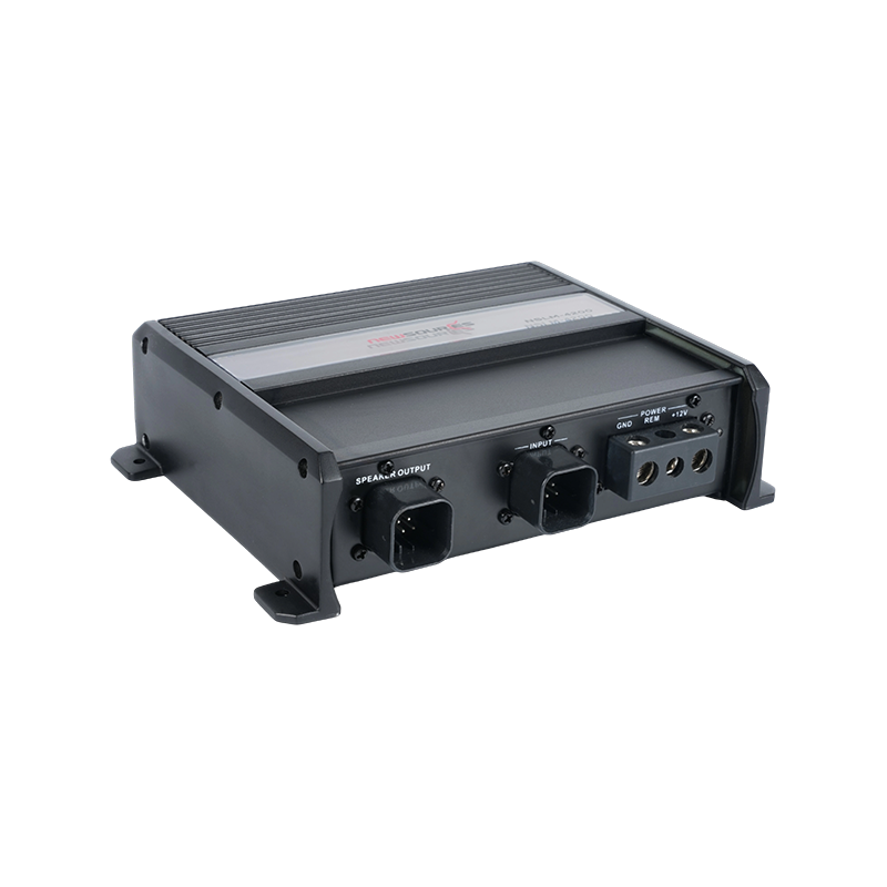
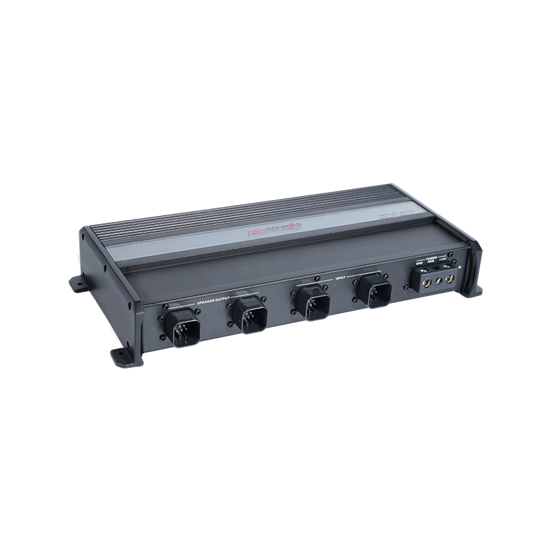
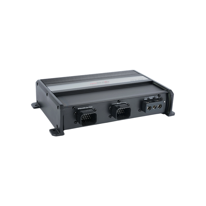
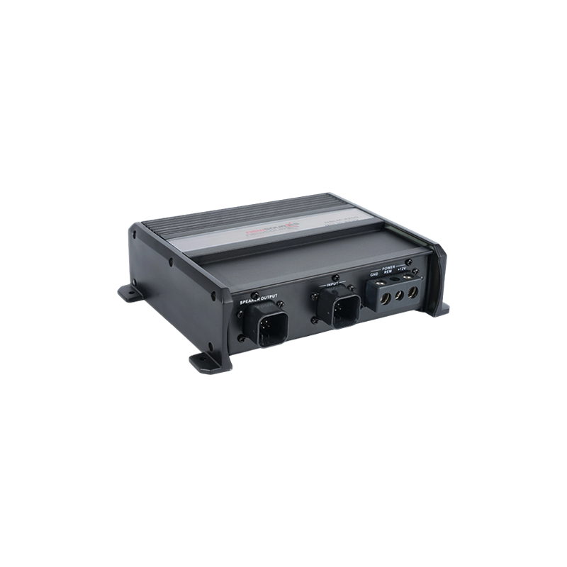
Car amplifiers are classified by their channel count and intended load. A two-channel amplifier powers a pair of speakers — typically front or rear — while a four-channel amplifier drives all four door speakers or a combination of speakers and a subwoofer using a bridged rear channel pair. A monoblock (Class D) amplifier is designed specifically for subwoofers, delivering high continuous power at low impedance with exceptional efficiency. Five-channel amplifiers combine a four-channel section for full-range speakers with a mono section for a sub, allowing a complete system upgrade from a single unit.
When matching amplifier power to your speakers, the amplifier's RMS power output per channel should be between 75% and 150% of each speaker's RMS power handling rating. Underpowering speakers causes the amplifier to clip — generating distorted square waves that damage tweeters and voice coils more reliably than overpowering ever would. Always work from RMS ratings, not peak power figures, which are marketing numbers with no practical relevance to real-world performance.
Also consider the amplifier's impedance compatibility. Most car speakers are 4-ohm nominal loads. Confirm that the amplifier is stable at 4 ohms per channel (or 2 ohms if you plan to wire speakers in parallel) before purchasing. Running an amplifier below its minimum stable impedance causes thermal shutdown, output stage failure, and voided warranties.
Tools and Materials You Need for a Car Amplifier Installation
A professional-quality amplifier installation requires the right materials from the start. Using undersized power cable, omitting the fuse holder, or relying on low-quality connectors are the leading causes of fire risk, poor sound quality, and premature component failure in DIY car audio installs. Assemble the following before beginning:
- Amplifier wiring kit: Available in 4-gauge, 8-gauge, and 0-gauge configurations. Match the kit gauge to your amplifier's total RMS wattage — 8-gauge for amplifiers up to 500W RMS, 4-gauge for 500–1000W RMS, and 0-gauge for systems above 1000W RMS total.
- Inline fuse holder and fuse: The power cable from the battery must be fused within 45 cm (18 inches) of the battery terminal. The fuse rating should equal or slightly exceed the amplifier's maximum current draw, calculated as total RMS watts divided by 12 volts.
- RCA interconnect cables: Shielded, twisted-pair RCA cables carry the low-level audio signal from the head unit to the amplifier. Longer runs (over 1.5 metres) demand high-quality cables with good shielding to prevent alternator whine and interference pickup.
- Remote turn-on wire: A thin wire (typically 18–22 gauge, included in most wiring kits) that connects the head unit's remote output (labelled REM or BLUE/WHITE) to the amplifier's remote terminal, switching the amp on and off with the head unit.
- Speaker wire: 16-gauge wire is adequate for most speaker runs under 3 metres. Use 14-gauge for longer runs or high-power applications to minimise resistive losses.
- Tools: Wire strippers, crimping tool, ring terminal connectors, electrical tape or heat-shrink tubing, a panel removal tool set, a drill with appropriate bits, and a multimeter for fault-finding.
Selecting the Best Mounting Location for Your Amplifier
Where you mount your car amplifier affects heat dissipation, wiring routing, and available boot or cabin space. Car amplifiers generate significant heat during operation — a Class AB amplifier running at full power converts roughly 50–65% of its input power to heat, meaning a 500W amplifier may dissipate 250W or more as thermal energy. The mounting location must allow adequate airflow across the amplifier's heat sink to prevent thermal protection shutdowns.
Boot Floor or Side Wall
Mounting the amplifier on the boot floor or side wall is the most common installation approach for hatchbacks, saloons, and SUVs. It minimises power cable length from the battery, keeps the amplifier accessible for adjustment, and allows the heat sink to dissipate into the open boot space. When mounting flat on the floor, ensure the amplifier is raised on a shallow platform or bracket to allow airflow beneath the chassis. Never mount an amplifier face-down against carpet — this blocks the heat sink entirely and will cause thermal shutdown within minutes of operation.
Under a Seat
Compact mono amplifiers and slim four-channel units are increasingly designed for under-seat installation, preserving boot space. Confirm that the amplifier's height clears the seat runners with the seat in its rearmost position before committing to this location. Ventilation is more restricted under seats, so this mounting position is best suited to efficient Class D amplifiers that generate less heat per watt of output. Avoid positioning the amplifier directly above the seat runner, where mechanical vibration can loosen connectors over time.
Custom Enclosure or Amp Rack
For multiple amplifiers or show installations, a custom-built MDF or aluminium amp rack mounted vertically on the boot side wall or on a subwoofer enclosure provides optimal airflow, a clean appearance, and easy access to gain and crossover controls. Vertical mounting with the heat sink fins running vertically is the most thermally efficient orientation, as it aligns with natural convective airflow.
Step-by-Step: How to Wire and Fit a Car Amplifier
With the amplifier location decided and materials assembled, the installation proceeds in a logical sequence. Working through each step in order avoids the most common wiring errors and ensures a safe, reliable result.
Disconnect the Battery First
Before touching any wiring, disconnect the negative terminal of the car battery. This eliminates the risk of short circuits during the installation and prevents accidental activation of airbag systems or other safety-critical electronics that share the vehicle's wiring. Keep the terminal disconnected for the entire installation until all connections have been made and verified.
Run the Power Cable from the Battery
Feed the main power cable from the battery's positive terminal, through the firewall (using an existing grommet or a new grommet-protected hole drilled through unused firewall space), along the sill under the door trim, and to the amplifier location. Keep the power cable on the opposite side of the car from the RCA signal cables — running power and signal cables parallel to each other along the same route is a primary cause of alternator noise entering the audio signal. Crimp a ring terminal onto the battery end of the cable and connect it to the positive terminal. Install the inline fuse holder within 45 cm of this connection and insert the correctly rated fuse.
Run the Ground Cable to a Solid Chassis Point
The ground connection is as important as the power connection — a poor ground causes noise, reduced power output, and instability. The ground cable should be as short as possible (ideally under 60 cm) and must connect to bare metal on the vehicle chassis, not to a screw through carpet or plastic trim. Use a star washer between the ring terminal and the chassis surface to cut through any surface coating and ensure a low-resistance metal-to-metal contact. The ground cable gauge must match the power cable gauge exactly.
Connect the Remote Turn-On Wire and RCA Cables
Route the remote wire from the head unit's remote output terminal to the amplifier's REM terminal. Then route the RCA cables from the head unit's preamp outputs — keeping them away from the power cable at all times — to the amplifier's RCA inputs. If your head unit does not have preamp outputs, a line output converter (LOC) can tap the speaker outputs and convert them to a low-level RCA signal, though a head unit with dedicated preamp outputs will always deliver better noise performance.
Connect the Speaker Outputs
Run speaker wire from the amplifier's output terminals to each speaker, observing polarity — connect positive to positive and negative to negative consistently on every speaker. Reversed polarity on one speaker relative to the others causes phase cancellation that significantly degrades bass response and imaging. Label each wire run clearly before routing to avoid confusion during final connection.
Car Amplifier Wiring Reference: Gauge, Fuse, and Power
The following table summarises the recommended wiring specifications for car amplifier installations based on total system RMS power output, helping you select the correct cable gauge and fuse rating for your specific setup:
| Total RMS Power (W) | Power & Ground Cable Gauge | Recommended Fuse Rating | Max Current Draw (A) |
|---|---|---|---|
| Up to 250W | 10 AWG (6 mm²) | 25–30A | ~21A |
| 250–500W | 8 AWG (10 mm²) | 40–50A | ~42A |
| 500–1000W | 4 AWG (25 mm²) | 80–100A | ~83A |
| 1000–1500W | 2 AWG (35 mm²) | 125–150A | ~125A |
| 1500W and above | 0 AWG (50 mm²) | 200A+ | 125A+ |
Setting the Amplifier Gain and Crossover Correctly
Once the amplifier is wired and the battery is reconnected, the final step is setting the gain, crossover frequencies, and bass boost controls. These settings are the most misunderstood part of a car amplifier installation, and incorrect settings are responsible for the majority of blown speakers and poor-sounding systems in otherwise well-installed car audio setups.
The gain control on a car amplifier is not a volume control — it is an input sensitivity adjustment that matches the amplifier's input stage to the output voltage of the head unit. Setting the gain too high causes the amplifier to clip before the head unit reaches maximum volume, producing distortion that damages speakers. The correct procedure is to set the head unit to 75–80% of its maximum volume, play a continuous test tone at 0 dB (available on audio calibration CDs or as a phone app), and slowly raise the amplifier gain from minimum until you hear distortion, then back it off slightly. This sets the gain to the highest clean level the system can produce.
The crossover settings determine which frequencies each amplifier channel reproduces. For a subwoofer channel, set the low-pass crossover to 80 Hz as a starting point — this rolls off frequencies above 80 Hz that a subwoofer cannot reproduce accurately. For full-range speakers driven by a four-channel amplifier, activate the high-pass filter and set it to 80 Hz to prevent the speakers from attempting to reproduce deep bass frequencies that require more excursion than their cones can manage without distortion or damage. Fine-tune these crossover points by listening critically and adjusting in 10 Hz increments until the bass and midrange blend seamlessly without a gap or overlap in the frequency response.
Finally, bass boost controls — typically a 0–12 dB boost centred at 40–60 Hz — should be used sparingly if at all. Even a 6 dB bass boost increases the power demand on the subwoofer channel by a factor of four at the boost frequency. Unless your subwoofer is significantly under-powered relative to the amplifier, leaving the bass boost at 0 dB delivers cleaner, more accurate bass reproduction and protects the subwoofer voice coil from thermal overload.
Common Car Amplifier Installation Mistakes to Avoid
Even experienced installers encounter problems if they overlook certain fundamentals. The following mistakes account for the vast majority of failed or underperforming car amplifier installations:
- Running power and RCA cables in parallel: This is the primary cause of alternator whine in car audio systems. Always route power cables down one side of the car and RCA signal cables down the opposite side, crossing them only at 90-degree angles if necessary.
- Using undersized ground wire or a poor ground location: A ground cable smaller than the power cable, or connected to a painted or rusty surface, creates a voltage drop that limits power output and introduces noise. Match ground wire gauge to power cable gauge and always connect to bare metal.
- Omitting or incorrectly fusing the power cable: A fuse protects the vehicle's wiring from fire if the power cable shorts to the body. Always install the inline fuse within 45 cm of the battery, correctly rated for the amplifier's current draw.
- Setting gain by ear at high volume: This invariably results in a gain set too high, causing clipping at moderate listening volumes where it is difficult to hear but easily capable of destroying tweeters and midrange drivers over time.
- Blocking amplifier ventilation: Mounting an amplifier face-down, covering it with carpet, or positioning it in a sealed enclosure without airflow will cause thermal shutdown during normal use and shorten the amplifier's service life significantly.